COLD CHAMBER / MT300
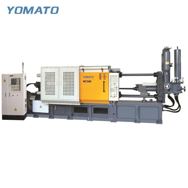
MT300 Die Casting Machine
The MT300 is a cold chamber option for aluminum, magnesium and copper alloy casting projects. Its 600x600 mm tie bar spacing is a useful starting measurement, but selection also depends on the closed die, injection system and the access needed during operation. Build the specification around those relationships.
Request an MT300 Quote ↗MT300 technical specifications
| Parameter | Unit | MT300 |
|---|---|---|
| Clamping Force | KN | 3000 |
| Platen Size (HxV) | mm | 950x950 |
| Space Between Tie Bars (HxV) | mm | 600x600 |
| Tie Bar Diameter | mm | 155 |
| Mold Height (Min.-Max.) | mm | 300-750 |
| Clamping Stroke | mm | 550 |
| Ejection Stroke | mm | 140 |
| Ejection Force | KN | 220 |
| Injection Force | KN | 500 |
| Injection Stroke | mm | 550 |
| Injection Position | mm | 0,-200 |
| Injection Plunger Diameter | mm | 60-90 |
| Injection Weight (Al) | KG | 3.0-6.0 |
| Casting Pressure (Intensify.) | MPa | 125-60.3 |
| Casting Area | cm2 | 240-500 |
| Max. Casting Area (40MPa) | cm2 | 750 |
| Casting Flange Protrusion | mm | 20-0.05 |
| Casting Flange Diameter | mm | 160 |
| Plunger Penetration | mm | 300 |
| System Working Pressure | MPa | 16 |
| Motor Power | KW | 30 |
| Oil Tank Capacity | L | 1000 |
| Machine Weight | KG | 15000 |
| Machine Dimensions (LxWxH) | m | 7.5x2.2x3.0 |
01 / SERIES
Use mounting faces as the height reference
MT300 accepts a listed mould height range of 300-750 mm. Establish this dimension from the complete tool assembly rather than adding only the cavity blocks. Mounting plates, ejector housings and adapters all affect the installed stack. The platen measures 950x950 mm, while the space between tie bars is 600x600 mm. Distinguish the supported tool outline from the route used to insert it. A slide or fitting may need to pass through a different part of that route, depending on the installation method. Include lifting points and the planned loading direction on the drawing. If a tool will be transferred from another machine, describe its present mounting and connection details so compatibility can be reviewed as an actual installation task.
02 / SERIES
Treat the feed system as part of the shot
The MT300 injection unit has a 60-90 mm plunger diameter range and a 3.0-6.0 KG aluminum injection weight range. A finished component weighing less than that upper figure is not, by itself, a completed selection check. The metal needed for runners and the remaining feed system must also be established. Describe the alloy and show the preliminary gate layout so the injection discussion has a defined target. Injection force is 500 KN and injection stroke is 550 mm. Consider those fields with the plunger arrangement and cavity geometry. Include details such as deep recesses, ribs and abrupt section changes in the enquiry. They help explain filling requirements that are not apparent from the component mass or overall external dimensions.
03 / SERIES
Coordinate opening and release rather than adding strokes
Clamping stroke and ejection stroke perform different jobs on MT300. The listed movements are 550 mm and 140 mm respectively. Show where the casting sits when the tool opens, when ejection begins and when a handler can take it away. These positions should be assessed with the runner still attached if that is how the component leaves the die. A removal path needs clearance for the gripping device as well as for the casting. Keep spray access visible in the same study, including surfaces around side actions. Any proposed extractor or sprayer should be discussed with the actual tool arrangement. This prevents the cell layout from assuming that every task can use the same opening direction and occupy the same space.
04 / SERIES
Arrange the cell around accessible interfaces
MT300 dimensions are 7.5x2.2x3.0 m, with a machine weight of 15000 KG. The production layout must extend beyond that envelope to accommodate operation, maintenance and peripheral equipment. Mark the position of the furnace relative to the shot sleeve, then identify the path toward conveying or trimming after extraction. Cooling and temperature control connections should remain reachable without placing equipment across the intended access route. For a machine quotation, supply the mould assembly, complete metal requirement, material and location of the project. A building plan is useful when installation access or the existing production line constrains placement. Explain any retained auxiliaries and their connections. Commercial order and delivery requirements can then be confirmed alongside a machine configuration grounded in the actual casting task. Where the same equipment will serve different tools, identify the expected changeover activities. Show how utilities disconnect, where the outgoing mould is moved and how the incoming assembly approaches the machine. This makes access requirements visible beyond the normal production cycle.
PROJECT ENQUIRY
Discuss your
casting project
Send your alloy, part drawing details, mould dimensions and project location. Confirm order quantity and delivery requirements with your quotation request.
Prefer email?
info@yomato-machinery.com