COLD CHAMBER / MT1100
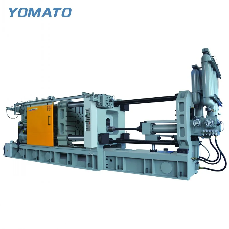
MT1100 Die Casting Machine
A useful MT1100 enquiry starts with the complete tool, including its mounting and service connections. This cold chamber machine serves aluminum, magnesium and copper alloy projects. Work through tooling fit, injection configuration and part removal separately, then bring those checks into a coherent production layout.
Request an MT1100 Quote ↗MT1100 technical specifications
| Parameter | Unit | MT1100 |
|---|---|---|
| Clamping Force | KN | 11000 |
| Platen Size (HxV) | mm | 1620x1600 |
| Space Between Tie Bars (HxV) | mm | 1050x1050 |
| Tie Bar Diameter | mm | 210 |
| Mold Height (Min.-Max.) | mm | 450-1150 |
| Clamping Stroke | mm | 900 |
| Ejection Stroke | mm | 190 |
| Ejection Force | KN | 500 |
| Injection Force | KN | 900 |
| Injection Stroke | mm | 900 |
| Injection Position | mm | 0,-300 |
| Injection Plunger Diameter | mm | 90-130 |
| Injection Weight (Al) | KG | 10.3-21.6 |
| Casting Pressure (Intensify.) | MPa | 141-67 |
| Casting Area | cm2 | 777-1622 |
| Max. Casting Area (40MPa) | cm2 | 2750 |
| Casting Flange Protrusion | mm | 20-0.05 |
| Casting Flange Diameter | mm | 240 |
| Plunger Penetration | mm | 350 |
| System Working Pressure | MPa | 16 |
| Motor Power | KW | 55 |
| Oil Tank Capacity | L | 1800 |
| Machine Weight | KG | 70000 |
| Machine Dimensions (LxWxH) | m | 11.2x3.4x4 |
01 / SERIES
Preserve the two platen dimensions
MT1100 lists a 1620x1600 mm platen and 1050x1050 mm tie bar spacing. Keep the platen dimensions in their stated orientation when assessing the mounting arrangement. The tie bar opening describes another boundary, especially during tool loading. Include the complete die outline, side actions and permanent fittings on the installation drawing. Its mould height window is 450-1150 mm, measured through the closed assembly between the intended mounting faces. Plates and adapters remain part of that stack even when they do not contribute directly to the cavity. Show access to the fixing points and connections in the mounted position. If the tooling is already in use elsewhere, explain the present interface and the intended loading direction so the comparison can address practical transfer requirements.
02 / SERIES
Use geometry to qualify the injection enquiry
The MT1100 injection unit lists a 90-130 mm plunger diameter range, with aluminum injection weights of 10.3-21.6 KG. Estimate the shot from the entire metal assembly, including the runner and other feed features. A finished component weight leaves those features outside the capacity discussion. Identify the alloy and describe the proposed gate arrangement with the part drawing. Injection force is 900 KN and injection stroke is 900 mm. Relate these fields to the intended injection configuration instead of combining isolated maximum values. Important details include changes in wall section, the location of ribs and the length of filling paths. If the project includes several tools, provide separate geometry and shot information for each rather than blending different requirements into a general machine brief.
03 / SERIES
Show the part beyond the ejector position
For MT1100, clamping stroke is 900 mm and ejection stroke is 190 mm. Review the complete movement from opening to the point where a handler has carried the casting clear. The release position is not necessarily the same as the final removal orientation. A gate or runner may determine where the assembly can be held and how it can travel through the open tooling space. Add the intended gripper to the drawing and show clearance to slides and cooling fittings. The spray task needs a separate approach to the die surfaces, which may place equipment in the same region at a different time. Describe the task sequence in the enquiry and identify retained handling equipment so its reach and interfaces can be discussed.
04 / SERIES
Allocate space for supporting equipment and people
MT1100 machine dimensions are 11.2x3.4x4 m, with a listed weight of 70000 KG. The occupied production area includes more than that main outline. Position the furnace according to metal transfer access and mark a clear destination for castings after extraction. Conveying, cooling and trimming may extend the process beyond the immediate machine boundary. Provide service access to the machine and practical routes for temperature control and release agent connections. The motor power is 55 KW, to be considered alongside separate peripheral requirements when reviewing utilities. Send the MT1100 casting drawing, alloy, mould dimensions and complete shot requirement with the project location. A floor plan and description of fixed obstacles help focus the configuration discussion on a layout that the site can accommodate. State whether the proposal is for a new cell or replacement of an existing machine. Replacement projects often have fixed surrounding equipment, making clear information about current interfaces, working positions and discharge routes particularly useful during the initial selection discussion.
PROJECT ENQUIRY
Discuss your
casting project
Send your alloy, part drawing details, mould dimensions and project location. Confirm order quantity and delivery requirements with your quotation request.
Prefer email?
info@yomato-machinery.com