COLD CHAMBER / MT350
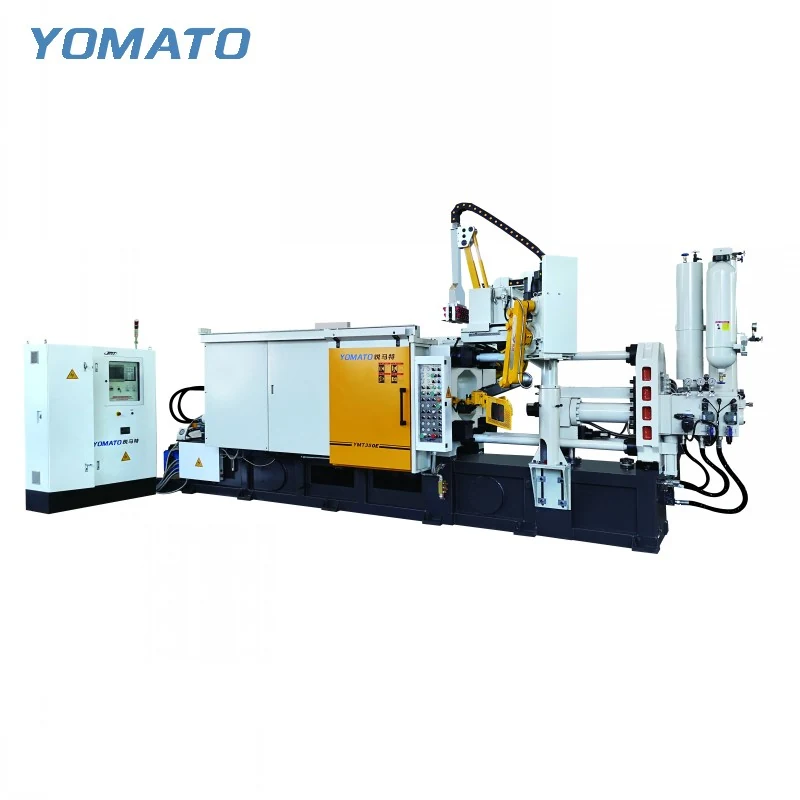
MT350 Die Casting Machine
MT350 enquiries benefit from a drawing that brings the tooling and handling route together. This MT cold chamber machine is intended for aluminum, magnesium and copper alloys. Compare the die envelope with its clamping space, then define the shot and peripheral equipment around the component you need to cast.
Request an MT350 Quote ↗MT350 technical specifications
| Parameter | Unit | MT350 |
|---|---|---|
| Clamping Force | KN | 3500 |
| Platen Size (HxV) | mm | 1020x1020 |
| Space Between Tie Bars (HxV) | mm | 650x650 |
| Tie Bar Diameter | mm | 165 |
| Mold Height (Min.-Max.) | mm | 300-800 |
| Clamping Stroke | mm | 600 |
| Ejection Stroke | mm | 150 |
| Ejection Force | KN | 240 |
| Injection Force | KN | 550 |
| Injection Stroke | mm | 600 |
| Injection Position | mm | 0,-210 |
| Injection Plunger Diameter | mm | 70-100 |
| Injection Weight (Al) | KG | 3.8-7.6 |
| Casting Pressure (Intensify.) | MPa | 125-60.3 |
| Casting Area | cm2 | 280-580 |
| Max. Casting Area (40MPa) | cm2 | 875 |
| Casting Flange Protrusion | mm | 20-0.05 |
| Casting Flange Diameter | mm | 170 |
| Plunger Penetration | mm | 320 |
| System Working Pressure | MPa | 16 |
| Motor Power | KW | 37 |
| Oil Tank Capacity | L | 1100 |
| Machine Weight | KG | 17500 |
| Machine Dimensions (LxWxH) | m | 8.0x2.3x3.1 |
01 / SERIES
Check how the tool is supported
The MT350 platen is 1020x1020 mm, and its tie bar opening is 650x650 mm. Use these measurements for separate questions: how the mould mounts, and how the assembly passes into position. The tooling drawing should identify mounting points, overhanging features and the connections that need access after installation. Mould height is listed at 300-800 mm. Measure the complete closed die with its permanent plates and ejection arrangement included. A tool can appear compatible in a frontal view while its installed depth or fittings create another problem. Supply both plan and side views where possible. If cooling hoses or slide connections are removable during loading, show their operating position as well as the temporary installation arrangement.
02 / SERIES
Explain the filling task behind the shot mass
The MT350 aluminum injection weight range is 3.8-7.6 KG, paired with a 70-100 mm injection plunger diameter range. Determine the metal quantity for the full shot rather than only the finished casting. The runner concept and overflow layout can materially change that quantity. Provide the intended alloy designation with the estimate, since an aluminum weight field should remain attached to the material it names. The machine table lists 550 KN injection force and 600 mm injection stroke. A configuration discussion should relate these to the tool layout, the intended plunger and the casting geometry. Highlight slender features, long filling paths or changes in section on the drawing. Those details make the injection requirement more specific than a broad application description.
03 / SERIES
Let part orientation guide removal planning
MT350 lists a 600 mm clamping stroke and 150 mm ejection stroke. Review the casting orientation at the end of ejection before choosing a discharge direction. A runner or gate attachment may determine where a gripper can hold the assembly and how it leaves the open die. Include those features in the handling drawing even if they will later be trimmed away. Die spraying needs its own access study because the surfaces to be reached may differ from the extractor approach. Consider the sequence of opening, release, removal and preparation for the next shot. Describe which tasks are intended to be automated, and bring any existing robot or sprayer details into the enquiry so their mounting and reach can be discussed.
04 / SERIES
Prepare a layout with service access
The listed MT350 machine dimensions are 8.0x2.3x3.1 m. Do not use that outline as the entire production cell boundary: a furnace, ladler, extractor and conveyor occupy their own working areas. Place each item according to the movement it performs and reserve access to machine connections. Temperature control lines and release agent supply should have understandable routes rather than crossing the operator position by default. The motor power field is 37 KW, which belongs in the machine portion of the utility review. A complete site schedule also considers separately selected peripherals. Send the MT350 request with the mould drawing, alloy, shot requirement and available layout. Explain any installation constraints and identify the destination of the casting after it leaves the machine. Explain whether downstream trimming occurs beside the machine or elsewhere in the facility. That choice changes the discharge handover and the path used to carry castings away, so it belongs in the initial layout brief rather than being left as a general handling assumption.
PROJECT ENQUIRY
Discuss your
casting project
Send your alloy, part drawing details, mould dimensions and project location. Confirm order quantity and delivery requirements with your quotation request.
Prefer email?
info@yomato-machinery.com