COLD CHAMBER / MT1300
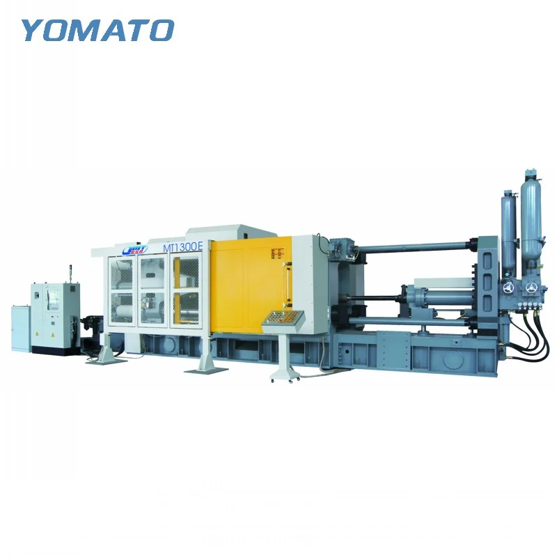
MT1300 Die Casting Machine
MT1300 planning brings the die, injection arrangement and surrounding equipment into the same engineering discussion. This MT cold chamber model is used within the range for aluminum, magnesium and copper alloys. Start with the specific component and tooling, then examine the material flow and access required by the proposed cell.
Request an MT1300 Quote ↗MT1300 technical specifications
| Parameter | Unit | MT1300 |
|---|---|---|
| Clamping Force | KN | 13000 |
| Platen Size (HxV) | mm | 1780x1770 |
| Space Between Tie Bars (HxV) | mm | 1100x1100 |
| Tie Bar Diameter | mm | 230 |
| Mold Height (Min.-Max.) | mm | 550-1200 |
| Clamping Stroke | mm | 1000 |
| Ejection Stroke | mm | 200 |
| Ejection Force | KN | 570 |
| Injection Force | KN | 1100 |
| Injection Stroke | mm | 950 |
| Injection Position | mm | 0,-320 |
| Injection Plunger Diameter | mm | 100-140 |
| Injection Weight (Al) | KG | 13.5-26 |
| Casting Pressure (Intensify.) | MPa | 140-71 |
| Casting Area | cm2 | 925-1815 |
| Max. Casting Area (40MPa) | cm2 | 3250 |
| Casting Flange Protrusion | mm | 25-0.05 |
| Casting Flange Diameter | mm | 240 |
| Plunger Penetration | mm | 350 |
| System Working Pressure | MPa | 16 |
| Motor Power | KW | 74 |
| Oil Tank Capacity | L | 2200 |
| Machine Weight | KG | 90000 |
| Machine Dimensions (LxWxH) | m | 12.5x3.5x4 |
01 / SERIES
Build a dimensional picture of the complete die
An MT1300 has a 1780x1770 mm platen and 1100x1100 mm tie bar opening. The platen dimensions are distinct, so retain their orientation on the tool layout. Mould height is listed at 550-1200 mm. Compare the full installed stack with that window, including permanent plates and adapters. A tooling drawing should also show slides, cooling manifolds and anything that projects beyond the main block. The insertion path can differ from the production position; identify the intended loading direction and any items connected afterward. Include access to mounting hardware and utility connections. This gives the enquiry a complete installation picture, rather than a simple comparison between cavity dimensions and machine size. Existing tooling should be accompanied by its present interface arrangement and relevant assembly views.
02 / SERIES
Put the feed system into the injection calculation
The MT1300 injection plunger diameter range is 100-140 mm, and the aluminum injection weight range is 13.5-26 KG. Develop the proposed shot estimate from the part together with runners, overflows and the biscuit arrangement. Describe the alloy clearly so the aluminum reference is not treated as the same mass capacity for every material. Injection force is 1100 KN and injection stroke is 950 mm. Read these fields with the intended plunger and gating layout, keeping the configuration discussion connected. Highlight the filling challenges in the component geometry, such as deep ribs, long paths or abrupt section changes. If the die design is not final, identify the provisional parts of the shot estimate so they can be reviewed as the tool develops.
03 / SERIES
Consider access at each stage of removal
The MT1300 lists a 1000 mm clamping stroke and 200 mm ejection stroke. Follow those movements with a drawing of the released casting and its intended gripper. Runners and projections should remain visible wherever they are still attached during extraction. Clearance needs to be checked against side actions, fittings and the opposite tool face. A removal route that suits the casting alone may not suit the complete handling assembly. Spraying requires access to the die surfaces after removal, so consider how the sprayer enters, works and withdraws. Describe the proposed order of operations and any auxiliary equipment already available for reuse. Sharing these details helps the machine enquiry address a working sequence rather than leaving the most constrained movements to a later layout exercise.
04 / SERIES
Arrange the cell around incoming and outgoing material
MT1300 machine dimensions are 12.5x3.5x4 m and its listed weight is 90000 KG. Incorporate that outline into the building plan together with installation access and service areas. The furnace and ladler define the incoming metal path, while the extractor, conveyor and trimming arrangement define what happens to the casting. Identify where those paths approach operating positions or fixed building features. Mould temperature control and release agent supply also require accessible connections. The 74 KW motor field belongs in the utility review alongside the separate auxiliaries. Request an MT1300 quote with the part revision, material, mould assembly and full metal requirement. Include the project location and equipment to be retained so the proposal can account for both new machinery and existing site constraints. Where a mould includes cooling circuits on several faces, identify the intended hose directions. Their operating positions can affect access for handling and spraying, so they belong in the tool and cell drawings used for the equipment review.
PROJECT ENQUIRY
Discuss your
casting project
Send your alloy, part drawing details, mould dimensions and project location. Confirm order quantity and delivery requirements with your quotation request.
Prefer email?
info@yomato-machinery.com