COLD CHAMBER / MT130
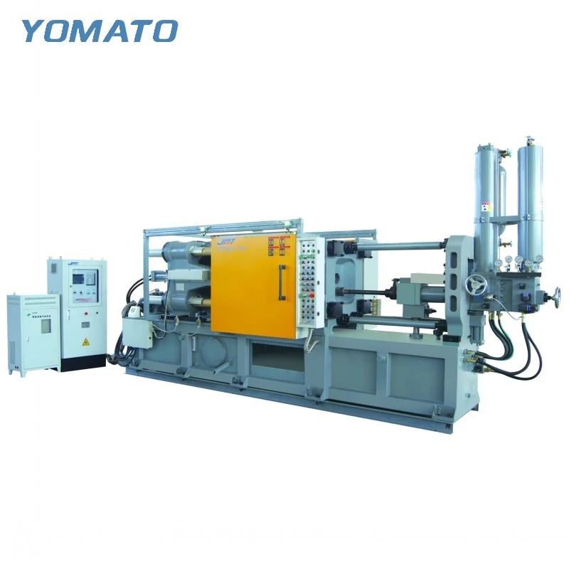
MT130 Die Casting Machine
The MT130 is a cold chamber machine for aluminum, magnesium and copper alloys. Its tooling envelope makes the complete mould drawing the right place to begin. Review installation, injection and removal requirements together before deciding how the machine should fit into your production area.
Request an MT130 Quote ↗MT130 technical specifications
| Parameter | Unit | MT130 |
|---|---|---|
| Clamping Force | KN | 1300 |
| Platen Size (HxV) | mm | 650x650 |
| Space Between Tie Bars (HxV) | mm | 420x420 |
| Tie Bar Diameter | mm | 110 |
| Mold Height (Min.-Max.) | mm | 200-550 |
| Clamping Stroke | mm | 380 |
| Ejection Stroke | mm | 90 |
| Ejection Force | KN | 120 |
| Injection Force | KN | 280 |
| Injection Stroke | mm | 380 |
| Injection Position | mm | 0,-150 |
| Injection Plunger Diameter | mm | 50-70 |
| Injection Weight (Al) | KG | 1.2-2.4 |
| Casting Pressure (Intensify.) | MPa | 125-60.3 |
| Casting Area | cm2 | 100-210 |
| Max. Casting Area (40MPa) | cm2 | 325 |
| Casting Flange Protrusion | mm | 20-0.05 |
| Casting Flange Diameter | mm | 120 |
| Plunger Penetration | mm | 200 |
| System Working Pressure | MPa | 14 |
| Motor Power | KW | 15 |
| Oil Tank Capacity | L | 600 |
| Machine Weight | KG | 7000 |
| Machine Dimensions (LxWxH) | m | 5.5x1.8x2.6 |
01 / SERIES
A small die still needs a complete fit check
The MT130 has a 420x420 mm opening between the tie bars and a 650x650 mm platen. These describe different boundaries. The opening concerns the route into the clamping area, while the platen supports the installed tool. Include mounting plates, projecting fittings and the proposed lifting arrangement in the assembly drawing. Looking only at the cavity block can miss the features that determine whether installation is practical. The mould height range is 200-550 mm. Establish the closed height with all permanent plates included, and show where cooling hoses leave the tool. A compact casting does not automatically require a compact mould; runners, slides and cooling passages can change the envelope substantially. Keep those features visible when comparing the drawing with the machine table.
02 / SERIES
Relate the shot sleeve to the whole metal requirement
MT130 injection plunger diameters range from 50-70 mm, with aluminum injection weights of 1.2-2.4 KG. These figures belong to the injection discussion rather than a finished component weight limit. The shot must also provide metal for the runner, biscuit and overflow arrangement. Prepare a mass estimate for that complete system and identify the alloy. A weight stated for aluminum should not be treated as the same weight capacity for every metal. Discuss the plunger selection alongside the gate arrangement and filling requirements. Thin ribs, recessed surfaces and changes in wall section are useful drawing details to highlight. They describe the casting task more clearly than a general request for a machine that makes small parts. Include any proposed cavity arrangement in that review.
03 / SERIES
Plan release into the available opening
The clamping stroke is 380 mm and the ejection stroke is 90 mm. Consider these movements in sequence: opening exposes the casting, and ejection releases it from the tool. A protruding runner or deep feature may affect the clearance needed even when the main component appears shallow. Draw the part in its released orientation, then add the gripper or manual handling access intended for the cell. Keep the removal path clear of the die connections. If a sprayer is proposed, its approach must also fit into the open tooling area. An open position that works for removal may still need a separate check for spraying both die faces. Explain the handling method in the enquiry so that tooling access and auxiliary equipment can be considered together.
04 / SERIES
Make the surrounding workspace useful
The machine dimensions listed for MT130 are 5.5x1.8x2.6 m. Use the machine outline as the starting footprint, then mark the service and operating zones around it. A furnace, ladler and discharge route each occupy space beyond the main body. Keep molten metal transfer separate from the route used to carry parts away, and identify where maintenance staff can reach connections. The listed motor power is 15 KW; a utility schedule should also account for the auxiliary equipment selected for the project. Share the building layout and existing equipment details when requesting an MT130 quotation. Useful attachments include the part revision, mould assembly, alloy designation and proposed furnace location. Where tooling is still being developed, describe the unresolved interfaces so the equipment conversation can focus on them. If the component is intended for hardware or electronic products, identify the surfaces and attachment features that matter in use. Keep the application explanation tied to the actual drawing so appearance, handling and tooling questions can be discussed without assuming identical requirements across a whole industry.
PROJECT ENQUIRY
Discuss your
casting project
Send your alloy, part drawing details, mould dimensions and project location. Confirm order quantity and delivery requirements with your quotation request.
Prefer email?
info@yomato-machinery.com